Romeo is from Argentina. At the beginning of this year, their customer customized a set of personalized hydraulic lifting equipment. The test run of the equipment was smooth. After the trial, the customer reported that the energy consumption of the equipment was a little high. After the inspection, the engineer found that the throttling loss of the hydraulic cartridge counterbalance valve is large when the load is low and the flow is large, which is the source of high energy consumption. They requested the manufacturer to optimize the hydraulic cartridge counterbalance valve. The manufacturer tried for 4 weeks but no result. Romeo contacted some other hydraulic cartridge valve manufacturers, but there was still no good plan. The customer had been pushing for update, Romeo had no idea yet and was very worried.
Romeo found me through the introduction of Patrick, an old customer of AAK. According to the situation described by Romeo, AAK technical team pondered the original hydraulic cartridge counterbalance valve drawing and system schematic diagram, 2 days later, the preliminary plan was formed. After 50 days, AAK sent 12 hydraulic cartridge counterbalance valve samples.
Last week, Romeo emailed us to inform that after AAK hydraulic cartridge counterbalance valve was installed in the equipment, the throttling was improved under low load and large flow. The energy consumption was 20% lower than before, the customer was very satisfied. Their engineers were surprised that AAK technical team optimized the original hydraulic cartridge counterbalance valve from these 3 aspects, and added a new function, namely, variable pilot ratio. The hydraulic cartridge counterbalance valve with variable pilot ratio has a special structure.
1. The optimized hydraulic cartridge counterbalance valve body is provided with a control oil port. The two ends of the control piston include the first acting surface and the second acting surface. The valve cage is provided with a first chamber which is close to the first acting surface.
2. The control piston is provided with an annular boss which is close to the end face of one side of the first chamber. One end of the valve spool is against the second acting surface, and the end cover is connected with the control piston in a sliding seal.
3. The end cover is also provided with an annular boss to form an annular groove of the sliding seal and a connecting oil passage, and the annular groove is close to the end face of one side of the first chamber. The second chamber is formed between the two working surfaces of the piston, which can easily realize the function of controlling the piston.
The optimized hydraulic cartridge counterbalance valve has the characteristics of variable pilot ratio and pilot pressure while the load moves stably. The performance of low pilot ratio and high pilot ratio can be realized according to different working conditions. The pilot pressure of the hydraulic cartridge counterbalance valve can be reduced by 20%, which is the highlight of 20% energy saving.
AAK hydraulic cartridge counterbalance valve, with variable pilot ratio and pilot pressure, you can also have a small trial!
AAK HYDRAULIC CARTRIDGE VALVES (445) 2022-12-19
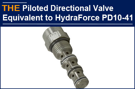
 Piloted directional valve equivalent to HydraForce PD10-41 passed testing, AAK received the more inquiries from customer in the United States
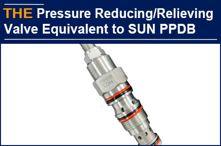
 For Pilot-Operated Pressure Reducing/Relieving Valve equivalent to SUN PPDB-LDN, AAK received the re-peat order from customer in Europe
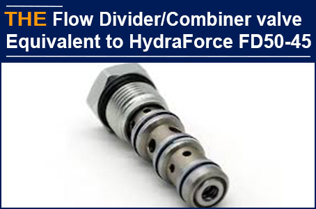
 For Hydraulic Flow divider/combiner valve equivalent to HydraForce FD50-45, AAK received the trial order from a Customer in the United States
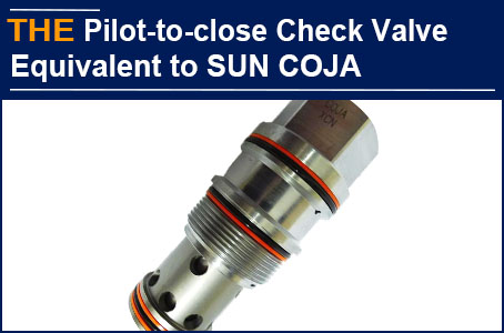
 For Hydraulic Pilot-to-close check valve equivalent to SUN COJA, AAK received the trial order from a Customer in Germany